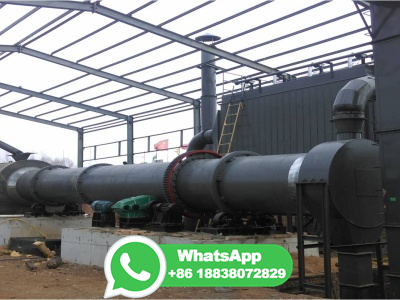
ball mill wiring block diagram

PDF MINI VERTICAL MILLING/ DRILLING MACHINE Harbor Freight

PDF MINI VERTICAL MILLING/ DRILLING MACHINE Harbor Freight

End Mill Capacity 1/2 inch Face Mill Capacity 1 inch Drill Capacity 1/2 inch ... parts list and diagram. Keep your invoice with this manual. Write the invoice number on the inside of the front cover. ... Adjusting the Limit Block (65) can control the travel of the Spindle Box. 1. Loosen Handle (30) attached to the Limit Block (65). ...

PDF Typical Electrical Drawing Symbols and Conventions. NRC

PDF Typical Electrical Drawing Symbols and Conventions. NRC

Basics 7 kV 3Line Diagram : Basics 8 AOV Elementary Block Diagram : Basics 9 kV Pump Schematic : Basics 10 480 V Pump Schematic : Basics 11 MOV Schematic (with Block included) Basics 12 12/208 VAC Panel Diagram : Basics 13 Valve Limit Switch Legend : Basics 14 AOV Schematic (with Block included) Basics 15 Wiring (or Connection ...

Process Control of Ball Mill Based on MPCDO Hindawi

Process Control of Ball Mill Based on MPCDO Hindawi

The flow diagram of the ball mill system is illustrated in Figure 1, including the ball mill, pump sump, hydrocyclones, and vibratory conveyor. Figure 1 . ... Block diagrams of modified DO. 4. Simulations. In this section, the threeinputthreeoutput model is firstly introduced. Then, the schematic diagram of MPCDO is illustrated.

10 Types of Milling Cutters: Uses and Selection Principles

10 Types of Milling Cutters: Uses and Selection Principles

These cutters come in different sizes, shapes, and materials. Some milling cutters are made of highspeed steel (HSS), while others are made with carbide tips. 1. End mill: The end mill is a cutting tool that has teeth on both sides. This tool is versatile and can be used for a variety of drilling operations.

Grinding Circuit Control Strategy 911 Metallurgist

Grinding Circuit Control Strategy 911 Metallurgist

Figure 4 is a schematic diagram of a ball mill/cyclone control system. This diagram shows the instrumentation and the calculated variables used in the control strategies. The prior detailed process analysis study produced two major conclusions: Reduce mill feed size Reduce ball charge size

Types of Electrical Drawings and Wiring Circuit Diagrams

Types of Electrical Drawings and Wiring Circuit Diagrams

A power wiring diagram, also known as an electrical power distribution diagram, is a schematic representation of an electrical system that specifically focuses on illustrating the distribution of electrical power within a facility, a complex electrical network or specific electrical circuit. It typically shows the connections and routes of ...

Crushing Plant Flowsheet DesignLayout 911 Metallurgist

Crushing Plant Flowsheet DesignLayout 911 Metallurgist

a) Maximum Feed Opening — 625MM (25 In.) b) Recommended Product Range — 100MM to 19MM (4 In. to ¾ In.) Short Head (Tertiary) Cone Crusher (Refer to Fig. 2): The Short Head Cone crusher is normally applied as a third stage crusher in plants designed for three or four stages of crushers.

Ball Mill Motor Power Draw Sizing and Design Formula 911 Metallurgist

Ball Mill Motor Power Draw Sizing and Design Formula 911 Metallurgist

Ball Mill Motor Power Draw Sizing and Design Formula. The following equation is used to determine the power that wet grinding overflow ball mills should draw. For mills larger than meters (10 feet) diameter inside liners, the top size of the balls used affects the power drawn by the mill. This is called the ball size factor S. The following ...

MASSO Documentation

MASSO Documentation

Mill Tool Calibration Steps; Work Offsets; Cutter Compensation Z Wear; Conversational Programming. Lathe Conversational Wizards; Mill Conversational Wizards; ... Wiring and Setup . MultiHead. Introduction; Main Spindle; Multi Spindle 1 4; Dry Run Laser Pointer; Laser Engraving/Cutting; Plasma Torch and MASSO DTHC; OXY Torch; WaterJet;

Ball Mill: Operating principles, components, Uses, Advantages and

Ball Mill: Operating principles, components, Uses, Advantages and

A ball mill also known as pebble mill or tumbling mill is a milling machine that consists of a hallow cylinder containing balls; mounted on a metallic frame such that it can be rotated along its longitudinal axis. The balls which could be of different diameter occupy 30 50 % of the mill volume and its size depends on the feed and mill size.

Thanks for Installing EdrawMax Edraw Edraw Software

Thanks for Installing EdrawMax Edraw Edraw Software

Explore More in Edraw Suite. Allinone diagramming tool for creating over 280 types of diagrams with no hassle. Collaborative and versatile mind mapping tool to capture, organize and share ideas visually. Beginnerfriendly design tool to help create visually striking infographics.

SPEX SamplePrep 8000M MIXER/MILL Operating Manual

SPEX SamplePrep 8000M MIXER/MILL Operating Manual

Page 17: Assembly Diagrams Parts 8000M Mixer/Mill DIAGRAM A (Base plate, motor, and clamp assembly) Item Part No. Description 33297 Clamp retaining spring assembly, including spherical bearings 22631 Aluminum Clad Plywood Base 53066 Pad for #22631 800013 Rubberlined Coil Springs, set of 3 800011 Z Bracket, set of 4 Motor ...

Ball milling: a green technology for the preparation and ...

Ball milling: a green technology for the preparation and ...

Ball milling is a simple, fast, costeffective green technology with enormous potential. One of the most interesting applications of this technology in the field of cellulose is the preparation and the chemical modification of cellulose nanocrystals and nanofibers. Although a number of studies have been repo Recent Review Articles Nanoscale Advances Most Popular Articles

PDF INSTALLATION MAINTENANCE MANUAL Productivity Inc

PDF INSTALLATION MAINTENANCE MANUAL Productivity Inc

(6) Accurate positioning by using the advanced LMguide and ball screw. (7) The greatest feed rate (36m/min) of axis in the world. (8) Minimized heat displacement in Xaxis by double pretension structure. (9) Stable bed structure of 45°. (10) Ensures rapid and easier operating by applying the FAUNC OiTB CNC of 32 bit.

CNC Milling Machine Axis Explained [Complete DIY Guide] CNCCookbook

CNC Milling Machine Axis Explained [Complete DIY Guide] CNCCookbook

The two names imply two purposes: Home: This is the "0" coordinate position for the axis. Limit: Better stop before we hit the limits and crash! For most machines, only one switch is used per axis, and it's a Home switch. The Limits are determined in software.

Big Crusher Schematic Diagram Of Ballmill | Crusher Mills, Cone Crusher ...

Big Crusher Schematic Diagram Of Ballmill | Crusher Mills, Cone Crusher ...

ball mill wiring block diagram BINQ Mining. Nov 26, 2012 · BINQ provides both small ball mill and big ball mill; . FIG. 1 is a schematic block diagram of an . process crusher. WIRING DIAGRAM / CIRCUIT BOARD .

Operation Performed On Milling machine With Diagrams

Operation Performed On Milling machine With Diagrams

1) Plain milling or slab milling. the plain and slab milling operation. It is a method of producing a plain, flat, horizontal surface parallel to the axis of rotation of the cutter. This is also called slab milling. This operation produces flat surfaces on the workpiece.

Hydraulic Power Unit Troubleshooting Guide Haas Automation Inc.

Hydraulic Power Unit Troubleshooting Guide Haas Automation Inc.

Corrective Action. Oil leaks. The hoses are split or the fittings are loose. Tighten the fittings or replace the hoses. The oil tank overflows. Diagnose the cause and drain the oil to the correct level. Coolant contaminated the oil. Check the coolant collector for blockage. Chuck or tailstock does not operate correctly.

Ball mill Wikipedia

Ball mill Wikipedia

A ball mill, a type of grinder, is a cylindrical device used in grinding (or mixing) materials like ores, chemicals, ceramic raw materials and paints. Ball mills rotate around a horizontal axis, partially filled with the material to be ground plus the grinding medium.

PDF Instruction Manual and Parts Lists for Horizontal and Vertical Milling ...

PDF Instruction Manual and Parts Lists for Horizontal and Vertical Milling ...

MILLING MACHINES MODELS 747·747VS·847·860 WELLS·INDEX CORPORA,TION MP 1M 10/ 75 Repr. ... Wiring Diagram W iring Diagram Base Ass'ys. 747 847 860 Col. 0' Arm Ass'y. Spindle Housing Ass'y 860 ... Do Not Overlubricate Ball Bearings. INSTRUCTION MANUAL WELLS INDEX MILL III. PRE LIMINARY INFORMATION

The Fundamentals of a Vertical Machining Center (VMC)

The Fundamentals of a Vertical Machining Center (VMC)

Manufacturing Industry. At Southern Fabricating Machinery Sales, we have a wide variety of Milling Systems and Vertical Machining Centers. Coupled with our staff's knowledge of these powerful systems, we can be your best source for Milling, Turning, EDM, Fabrication and Plastics machinery. Call us today at or visit us on the web at ...

Name already in use GitHub

Name already in use GitHub

sbm ball mill schematic diagram miningGrinding control strategy on the conventional milling. 2009 8 27 · by a ball mill in product ( 9 mm) is fed to

Schematic of conventional ball Milling Device | Download Scientific Diagram

Schematic of conventional ball Milling Device | Download Scientific Diagram

Download scientific diagram | Schematic of conventional ball Milling Device from publication: Manufacturing Methods, Microstructural and Mechanical Properties Evolutions of HighEntropy Alloys: A ...

All about wiring of electric motors | EEP Electrical Engineering Portal

All about wiring of electric motors | EEP Electrical Engineering Portal

A distinction is drawn between: All about wiring of electric motors (photo credit: ) Block diagram Simplified representation of a circuit with its main parts. It shows how the electrical installation works and how it is subdivided. Circuit diagram Detailed representation of a circuit with its individual ...

PDF MODULE #5: FUNCTIONAL PERFOMANCE OF BALL MILLING Metcom Tech

PDF MODULE #5: FUNCTIONAL PERFOMANCE OF BALL MILLING Metcom Tech

Define and calculate the grinding efficiency of the ball mill in a ball mill circuit. Relate overall ball mill circuit output and circuit efficiency to specific design and operating variables. Compare sets of circuit survey data in terms of the elements of the functional performance equation.